From the plans to a 3D model, the reinforcement and the formwork
How a basement request runs through FlowCraft: the architect's and the engineer's plans, a 3D model on the ground plan, the assumptions, a remark that changes the model, the quantities, the reinforcement plan for one wall and the formwork.
FlowCraft automates entire business processes, from the request that comes in to the invoice that goes out. For a basement builder, that starts with the plans from the architect and the structural engineer.
How a basement request runs
The same basement as in the video, step by step.
1. The plans come in
The request arrives with two PDFs. The architect’s sheet carries the elevations and Section AB; the engineer’s ground plan (scale 1:50) carries a detail of every beam. The platform turns them into a project and keeps the plans with the request.

2. A 3D model on the ground plan
On that ground plan the platform builds the basement. The 30 cm floor slab slides in under the plan, so you keep seeing the plan while the walls rise. Then come eight 40 cm concrete walls, 14 masonry walls, five columns and 14 beams.
The hollow-core slabs bear 14 cm on the outer walls, which stop under the slabs. Above every lintel the masonry continues up to the underside of the slabs.
Where a steel beam bears on a concrete wall, like the HEB260 on the west wall, the model cuts a pocket in the wall around the profile.
3. The sections beside the source
In the viewer you put the model next to the plans. The architect’s Section AB sits beside the same section through the model, with the wall, the floor slab and the hollow-core slabs hatched.
For the beams, the detail of L04, an HEB160 within the hollow-core slabs, sits beside the section through that beam.


4. What the plans don’t say
Not everything is on the plans. What the platform assumed is shown in the viewer on the element itself, and listed here.
- A1 The 242 cm height on Section AB is measured from the top of the structural floor slab; the basement gets no screed.
- A2 The floor slab projects 150 mm beyond the outer face of the walls. That is not on the plans; it is derived from the survey’s 170.17 m² (161.7 m² inside the outer outline plus a 55.96 m perimeter × 0.15).
- A3 The inner walls are 14 cm load-bearing masonry, according to the legend. The block type is not on these plans.
- A4 The hollow-core slabs bear 14 cm on the outer wall, which stops under the slabs. The survey counts the same way: 147.4 m² up to the bearings.
- A5 The top of lintel B01 is at −0.56: detail B01 shows about 16 cm of masonry between the underside of the hollow-core slabs (−0.40) and the 25 cm lintel, scaled off the detail. The doors then have 2.01 m of clear height (lintel underside −0.81).
- A6 The stair opening is the drawn stair outline between the walls. The layout of the hollow-core slabs is not drawn.
- A7 K02 and K03 are L-shaped on the plan (14 × 30 plus a 16 × 14 stub). The long leg is modelled and the stub left out, 0.003 m³ per column.
- A8 L01 and L03 are lintels in the masonry: underside −0.77, read off the detail. The wall openings below them are 2.05 m high.
- A9 The 959 mm opening in the wall between column K03 and the cross wall has no lintel on the plan. None is modelled: no lintel and no wall above it, so the opening runs full height between two separate walls.
- A10 The model has no separate lintel element, and a beam needs two supports. Every wall with a lintel opening is therefore split at the opening and the lintel rests on the two parts. The masonry between lintel and hollow-core slabs, about 16 cm over B01 and 24 cm over L01 and L03, is a wall of its own over the opening, up to the underside of the slabs.
- A11 K01 carries the end of L06: the beam stops short of the column’s centre. The top of K01 therefore sits against the underside of L06, at −0.46.

5. A remark, and the model follows
If something is wrong, you put a remark on the element. Here that is “verlaag muur 10 cm” (lower the wall by 10 cm) on west wall W-W2, with 2,320 mm as the new wall height instead of 2,420 mm.
The model follows: the concrete walls, the lintels and the hollow-core slabs drop by 10 cm and the clear height becomes 2.32 m. The quantities and the drawings below come from that updated model.

6. Quantities from the model
The quantities come straight from the model. Next to them is the engineer’s survey, taken off the plan as drawn.
| Item | Model | Engineer |
|---|---|---|
| Floor slab 30 cm | 51.05 m³ | 51.05 m³ |
| Outer walls, concrete 40 cm | 50.44 m³ | 54.17 m³ |
| Inner walls, masonry 14 | 9.69 m³ | – |
| Columns K01–K05 | 0.77 m³ | 1.02 m³ |
| Lintels B01 · 4 pieces | 0.168 m³ | 0.235 m³ |
| Hollow-core slabs up to the bearings | 147.4 m² | 147.4 m² |
| Hollow-core slabs, less stair and hatch | 139.7 m² | – |
| Steel profiles L01–L10 | 1,388 kg | – |
The hollow-core slabs bear 14 cm on the outer walls, in the model and in the survey. The engineer worked with a clear height of 2.42 m; the model, after the remark, has 2.32 m.
7. A section in the wall
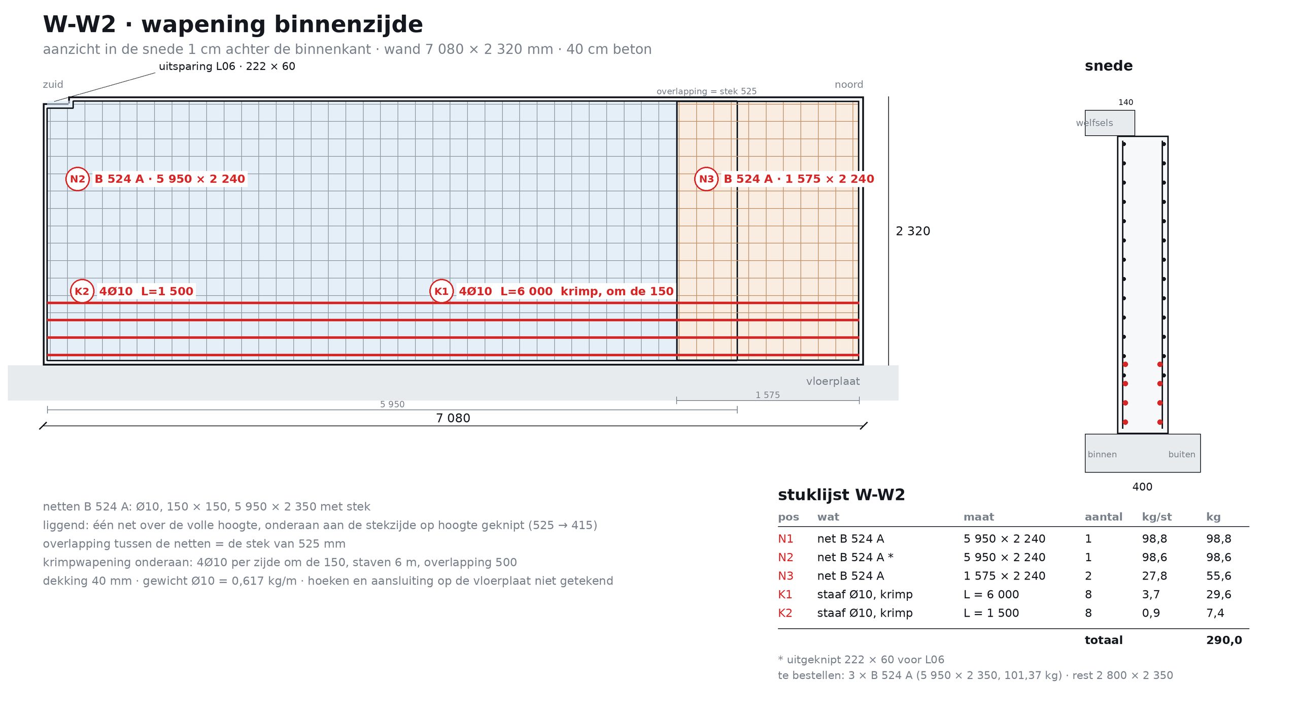
For production, the viewer cuts a section parallel to wall W-W2, 1 cm behind its inner face. That shows the whole wall: 7.08 m long and 2.32 m high, with the pocket for the HEB260 at the top.

8. The reinforcement plan for this wall
On that section the platform draws the reinforcement: B 524 A meshes on both faces, Ø10 at 150 × 150, 5,950 × 2,350 mm, with the bars projecting 525 mm on one long and one short edge for the lap. The mesh lies with its long side along the wall and is cut to height on the projecting edge at the bottom, so one mesh runs from bottom to top. The next mesh laps the projecting bars and is cut to fit. Under the pocket the first mesh has a cut-out.
At the bottom there is shrinkage reinforcement: four Ø10 bars per face, 150 mm apart. Every position gets a mark, a count and a size, as on a reinforcement plan from an engineering office. The schedule lists 4 mesh pieces cut from 3 B 524 A meshes and 16 shrinkage bars, 290.0 kg in total.
Drawn with 40 mm cover, B 524 A meshes lapped on their projecting bars and 6 m shrinkage bars lapped 500 mm. The corners and the connection to the floor slab are not drawn.
| Piece | Count | kg |
|---|---|---|
| N1 · B 524 A mesh, 5,950 × 2,240 | 1 | 98.8 |
| N2 · B 524 A mesh, cut-out 222 × 60 for L06, 5,950 × 2,240 | 1 | 98.6 |
| N3 · B 524 A mesh, cut to fit, 1,575 × 2,240 | 2 | 55.6 |
| K1 · Ø10 bar, shrinkage, L = 6,000 | 8 | 29.6 |
| K2 · Ø10 bar, shrinkage, L = 1,500 | 8 | 7.4 |
| Total · to order 3 × B 524 A | 290.0 |
9. The formwork with PERI panels
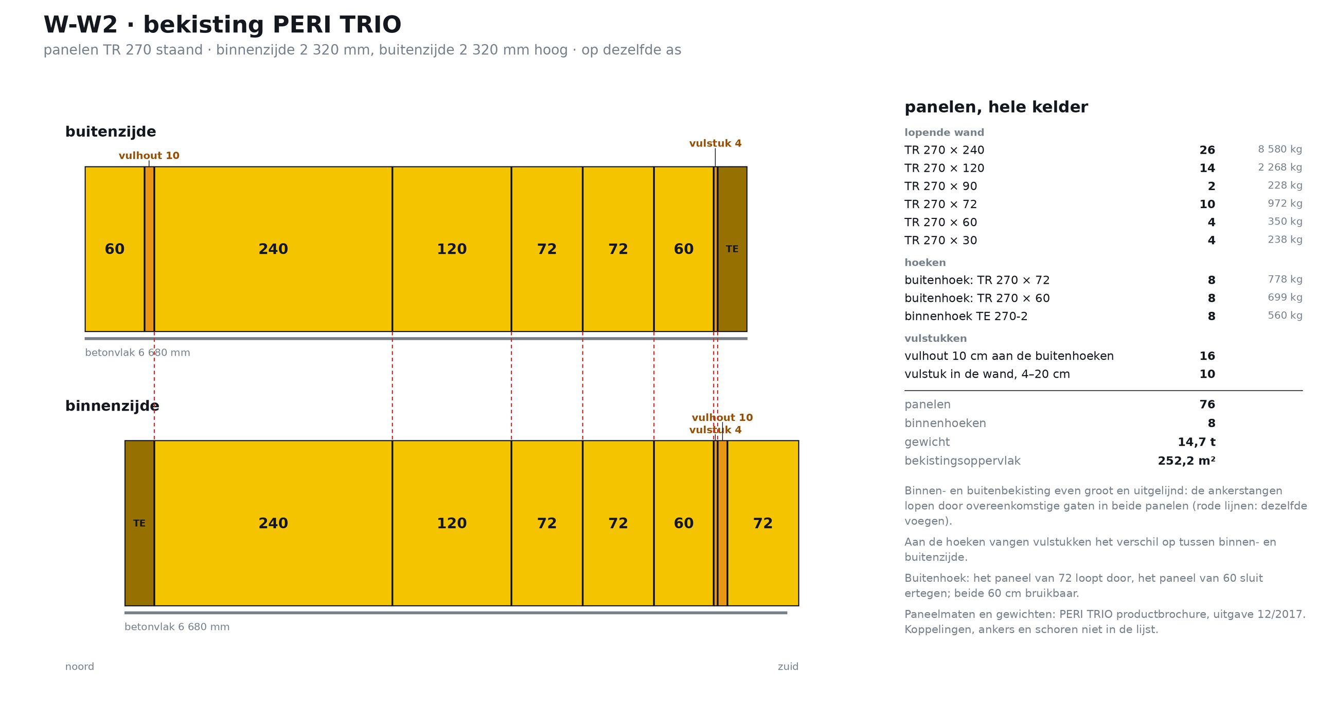
For the same basement the platform lays out the formwork with 2.70 m PERI TRIO panels. The inner and outer formwork are the same size and aligned, so the tie rods run through matching holes in both panels.
The corners are closed. At an outside corner the 72 cm panel runs past and the 60 cm panel closes against it, so both give 60 cm of usable face. On the inside there is a corner panel. The inner face is shorter than the outer face; fillers at the corners take up the difference.

| Panels for the whole basement | Count |
|---|---|
| TR 270 × 240 | 26 |
| TR 270 × 120 | 14 |
| TR 270 × 90 | 2 |
| TR 270 × 72 | 10 |
| TR 270 × 60 | 4 |
| TR 270 × 30 | 4 |
| Outside corner: TR 270 × 72 and × 60 | 8 + 8 |
| Inside corner TE 270-2 | 8 |
| 10 cm timber filler at the outside corners | 16 |
| Fillers within the wall, 4–20 cm | 10 |
| Total | 76 panels + 8 inside corners · 14.7 t · 252 m² |
Panel sizes and weights from the PERI TRIO product brochure, issue 12/2017. Couplers, ties and props are not in the list.
Does this fit the way you work?
How does a basement quotation come about at your company, and how much time goes into measuring a plan? We are happy to come and talk about it. Half an hour is enough to see whether this fits. Plan a conversation.